Learn Circuits Fast (ryce-box-0)
Use with the assistance of an adult. Like all electronics, components may be broken or may heat up if used incorrectly. Be careful with inserting/removing symbols. Do not modify circuits without turning them off first. Do not connect VCC to GND. Be especially careful with gates.
Let’s learn circuits fast!
Circuits are devices that use electricity to do things.
Step 1 – Get A Gridboard
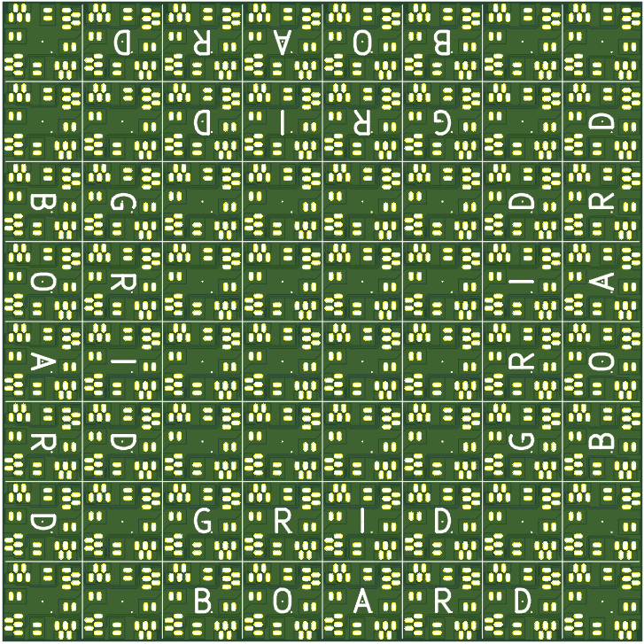
This is a Gridboard. It’s the easiest way to make circuits.
Make sure it doesn’t say “wrong side” on top.
This is a symbol. Circuits are made by combining symbols.
Be careful and gentle!
| Putting in | Taking out |
 |  |
Step 2 – Obtain Electricity
This symbol supplies electricity. Snap it into the gridboard anywhere you’d like. (powusb2-gb-0)
Electricity flows from high to low, like a waterfall.
“Low” is called GND or ground.

“High” is called VCC.
VCC is five Volts higher than Ground. We say that VCC is 5V and GND is 0V.
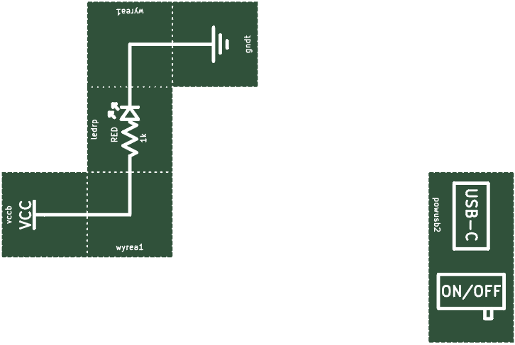
Step 3 – Make Circuits! (led-gb-0)
MAKE SURE TO ALWAYS TURN THE POWER OFF BEFORE YOU MAKE/CHANGE A CIRCUIT!

You just made your first circuit. Great job!

Like a clogged pipe, resistors slow the flow of electricity.
LEDs convert electricity into light.
Electricity flows from VCC, through a resistor, through an LED, and then to ground.
We need the resistor because too much electricity going through the LED would blow it up.
The amount of electricity passing through per second is measured in Amps or Amperes.
Wires are drawn with lines.
What Are Circuits Made Of?
Normally, circuits are made up of components connected together with wires.
Gridboard Symbols contain one or more components.
Wires are drawn with lines. Components are drawn with shapes.
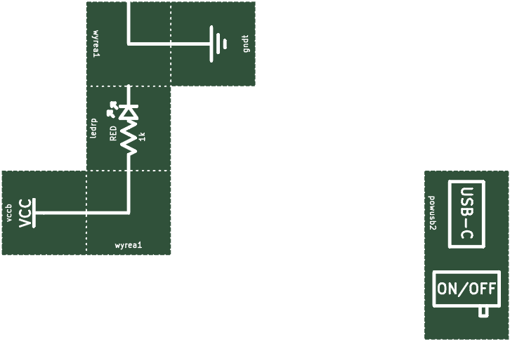
Unusual LED (led-2-gb-0)
It doesn’t matter which way or where on the Gridboard you put symbols (unless otherwise stated).
Broken Circuit (led-3-gb-0) (Circuit 3)
This circuit is broken, as there isn’t a complete path for electricity to flow.
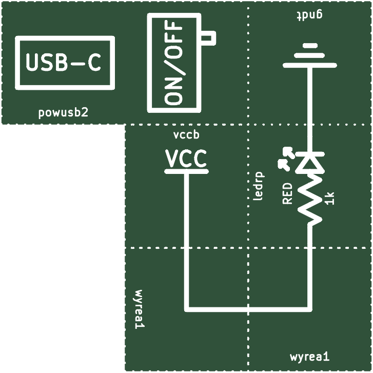
Long Wire (wyre-long-gb-0)
It doesn’t matter how long a wire is (for us).
Extra Wires (wyre-extra-gb-0)
It doesn’t matter if wires go to nowhere.
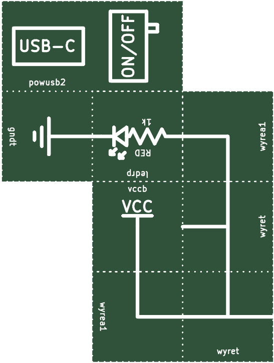
Components typically have one or more pins. The red LED has two pins on it.
If a wire/pin is disconnected, we call that pin floating.
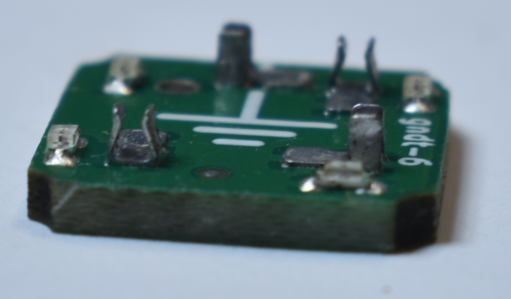
Backwards LED (led-6-gb-0)
LED stands for Light Emitting Diode. A diode only allows current to flow in one direction.
Backwards/Forwards LED (led-4-gb-0)
Another example showing LEDs are both lights and diodes.
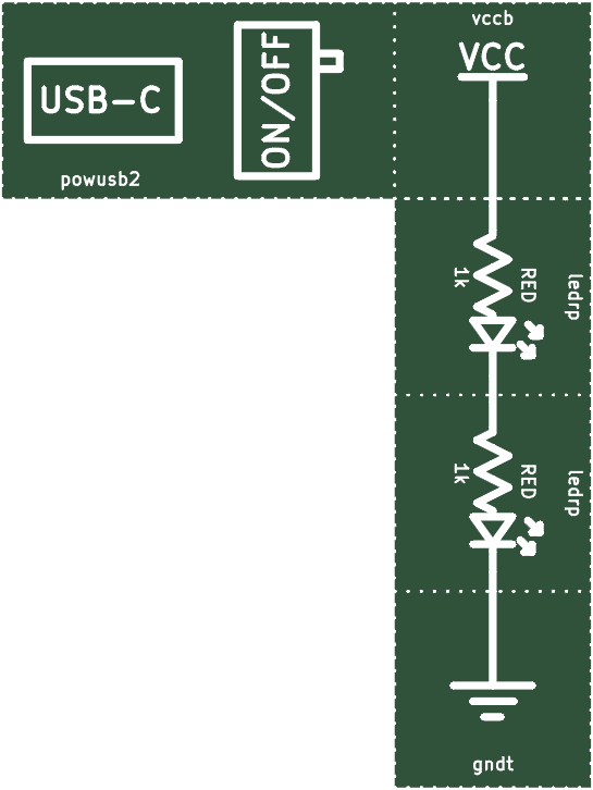
Series LEDs (led-series-2-gb-0)
Electricity goes through both LEDs. These LEDs are in series. Starting at VCC, we have 5V. Each LED loses about ~2V or so. Since the voltage gets lower and lower, the LEDs become less bright.
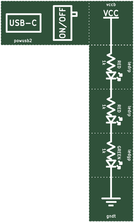
Three Series LEDs (led-series-3-gb-0)
Three LEDs may not even light up.
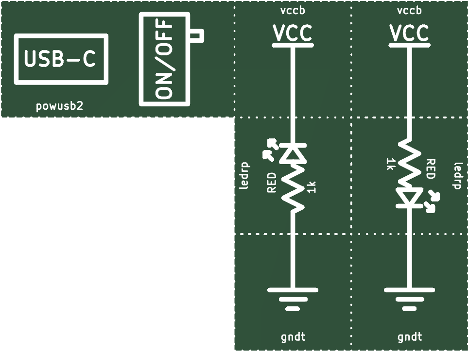
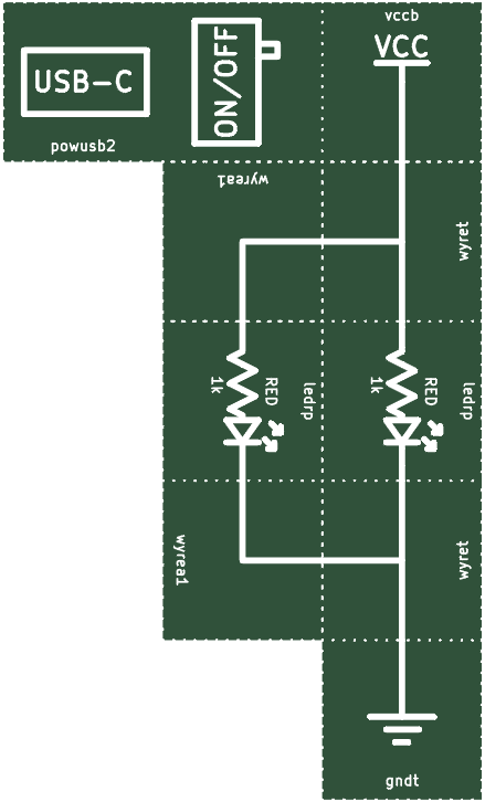
Parallel LED (par-gb-0)
These LEDs are in parallel. Notice the difference in brightness when compared to LEDs in series.
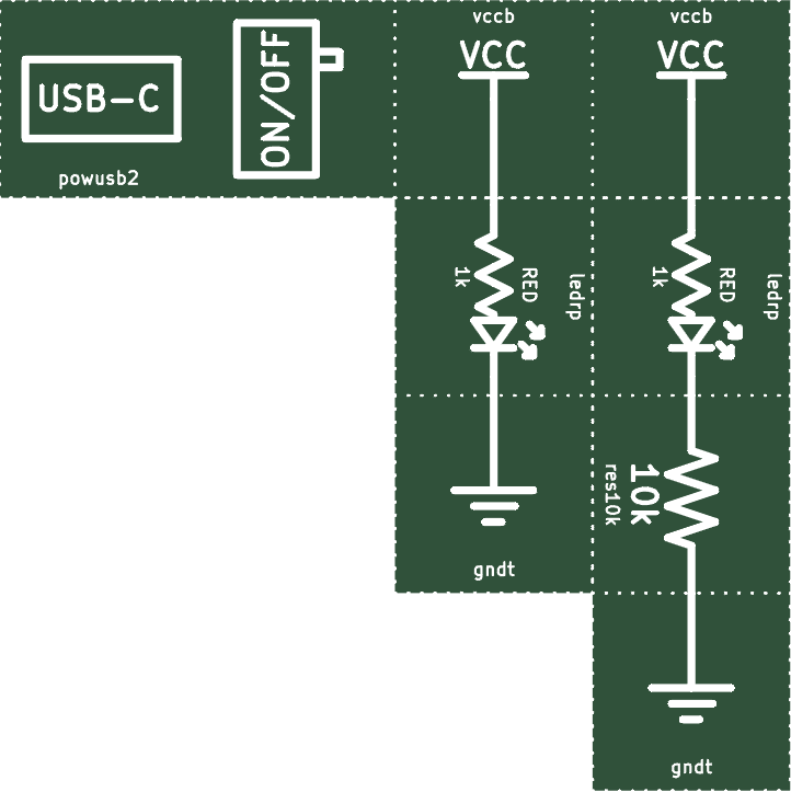
Dim LED (led-dim-gb-0)
The higher the value of a resistor, the more it resists current. Less electricity can get to the LED, making it dimmer.
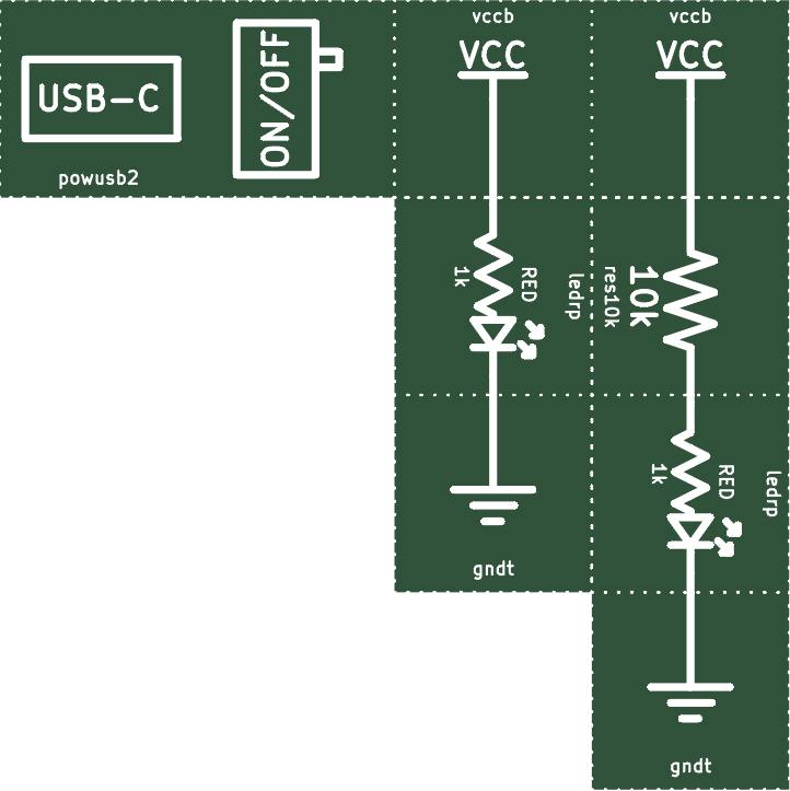
Dim LED Reordered (led-dim-2-gb-0)
It doesn’t matter what order the resistors and LEDs are in in this case.
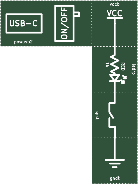
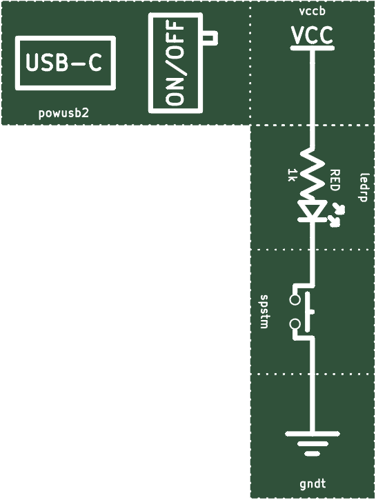
SPST (led-sw-gb-0)
The switch stops electricity from flowing if shut off. This type of switch is called a SPST switch. This type of SPST switch is called a toggle switch.

Reversed SPST (led-sw-2-gb-0)
The SPST switch still functions if placed after the LED.
Momentary SPST (led-swm-gb-0)
This is another type of SPST switch, called a momentary switch.
Next, try placing the switch before the LED.
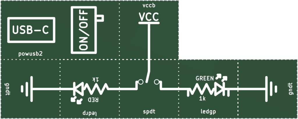
SPDT (led-spdt-gb-0)
SPST stands for Single-Pole Single-Throw. This is an example of a SPDT switch, or Single-Pole Double-Throw.

SPDT Simplified (led-spdt-2-gb-0)
The length of wires doesn’t matter.
A Potentiometer or Pot is a resistor you can change. The brightness changes as you rotate the pot.
Pot (led-pot-gb-0)
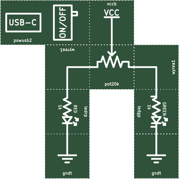
Unusual Pot (led-pot-broke-gb-0)

The top wire on a pot is called the wiper.
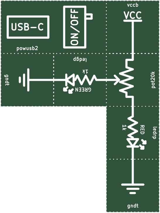
The resistance only changes between the wiper and the other pins on the pot. Thus, only one LED changes brightness.
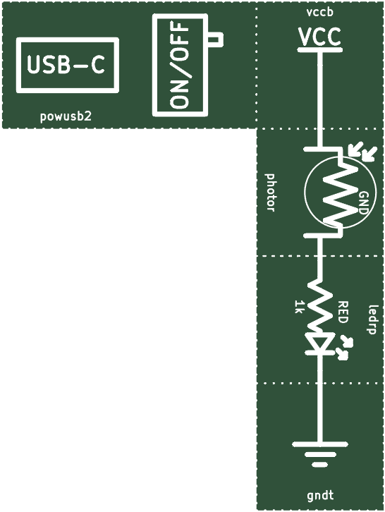
Photoresistors (led-photor-gb-0)
A photoresistor changes its resistance based on how bright it is. If it is bright, the resistance is low. If it is dark, the resistance is high.
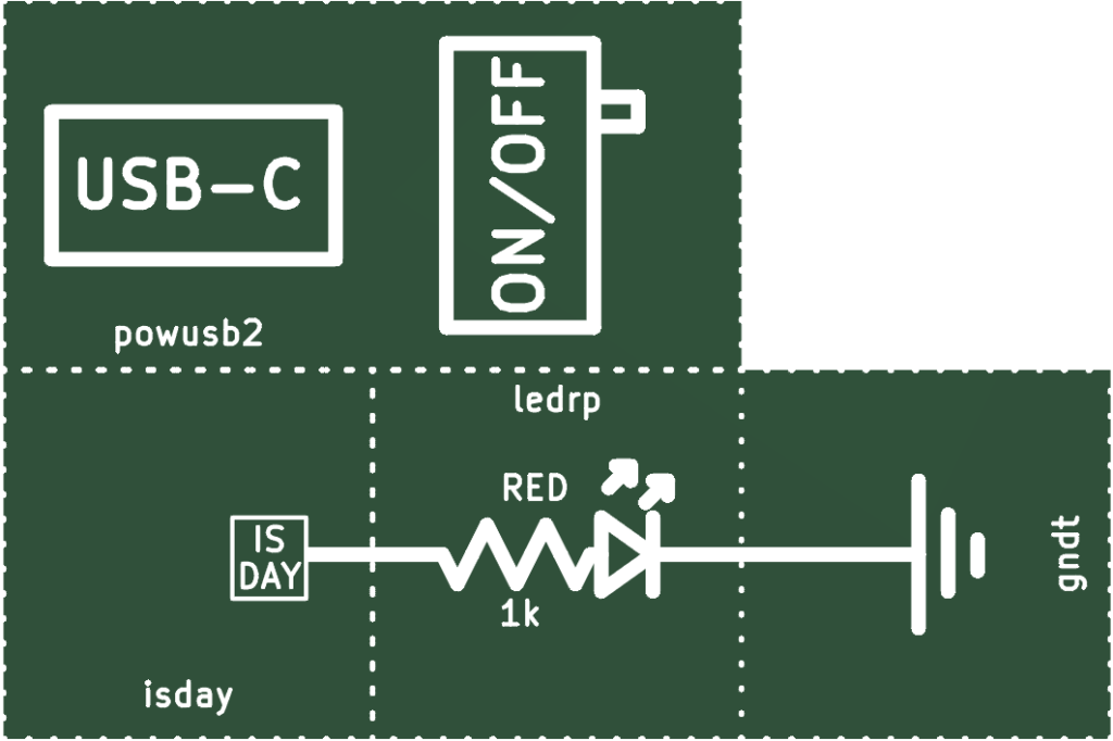
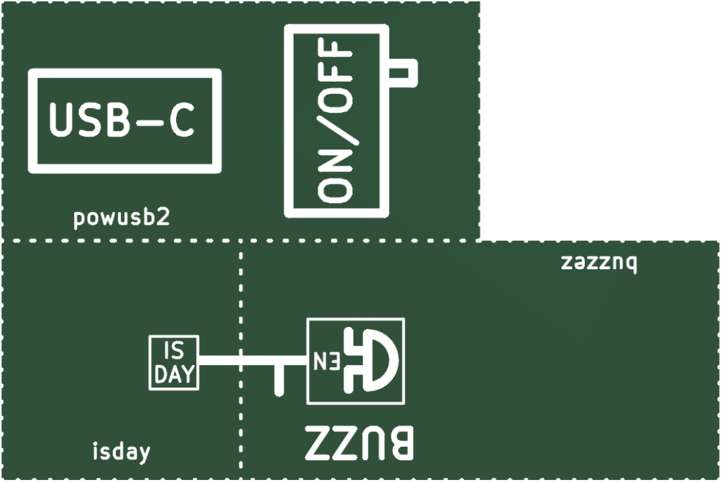
Daylight Sensor (isday-gb-0)
The isday symbol uses a photoresistor to output 5V (VCC) when on, and 0V (GND) when off.
LED On/Off (led-onoff-dum-gb-0)
Another way to turn on/off an LED.
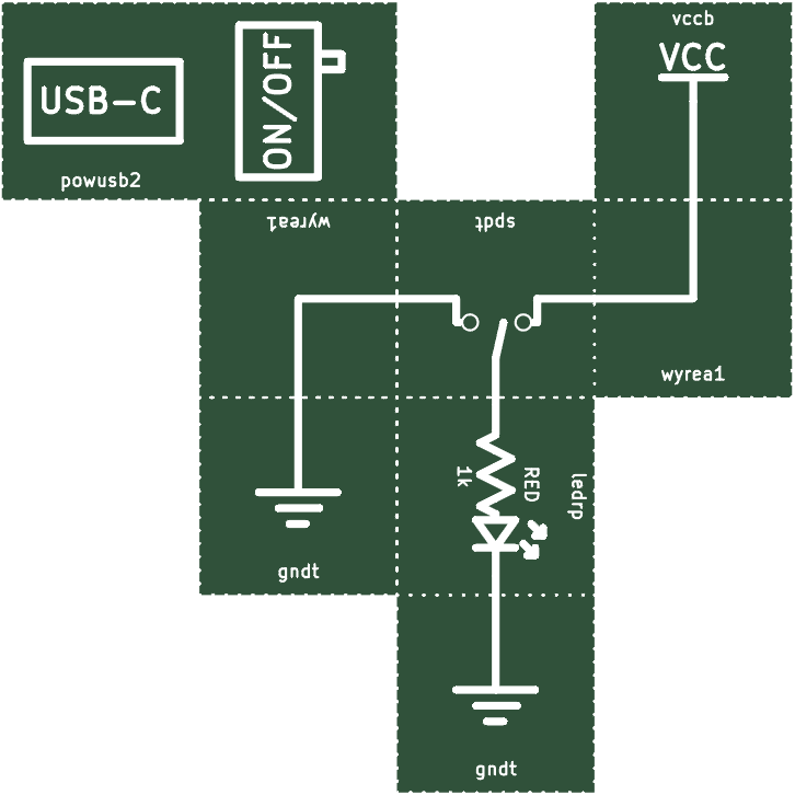
Being able to swap between VCC and GND becomes very useful later.
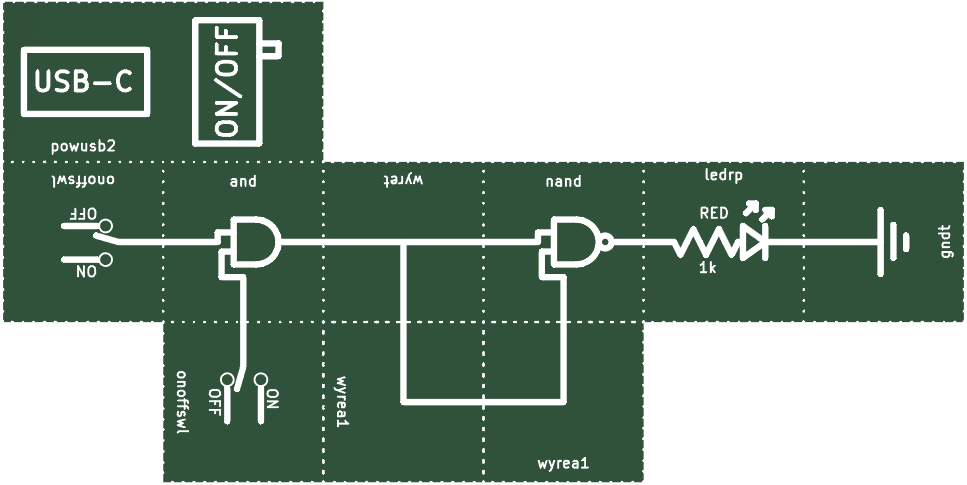
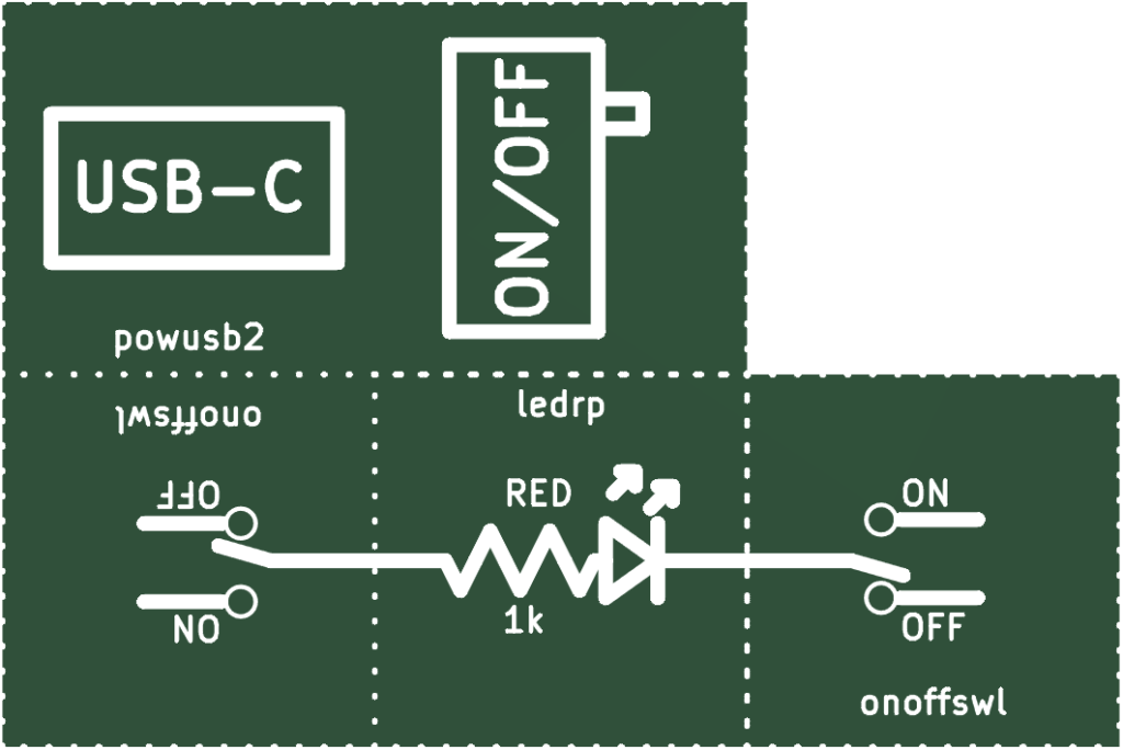
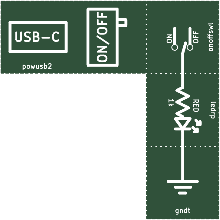
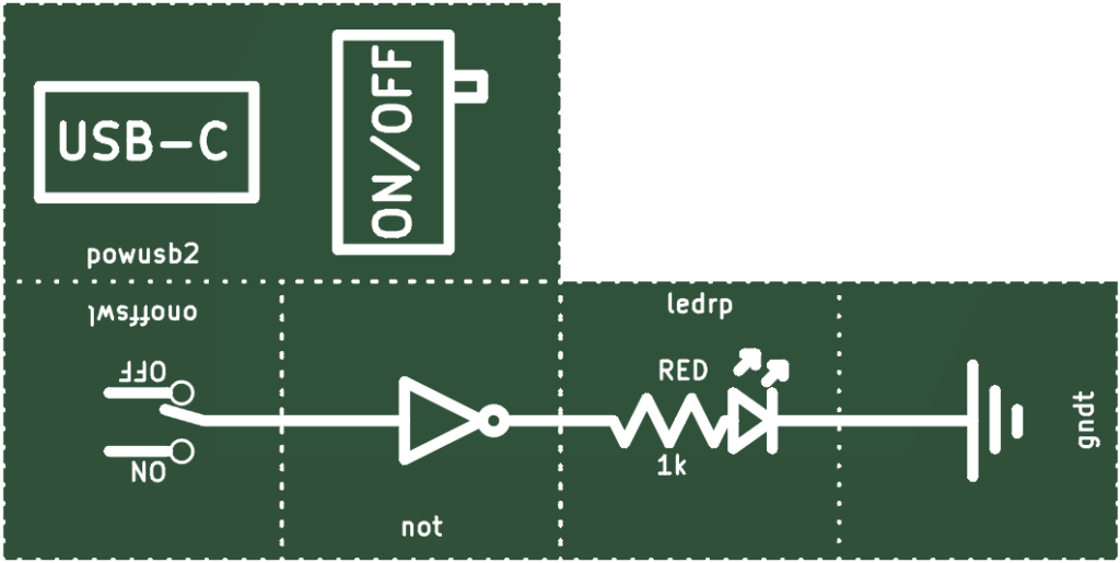
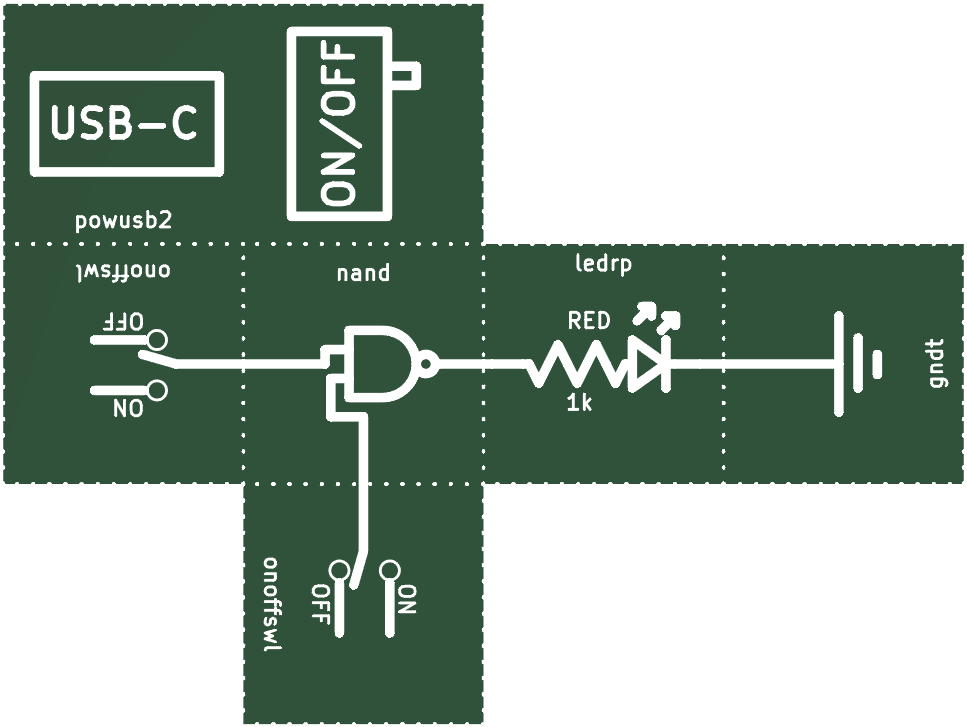
LED On/Off Simplified (led-onoff-gb-0)
The onoffswl symbol switches between VCC and GND.
LEDs As Diodes (led-5-gb-0)

Bidirectional LED (ledbirgp-gb-0)

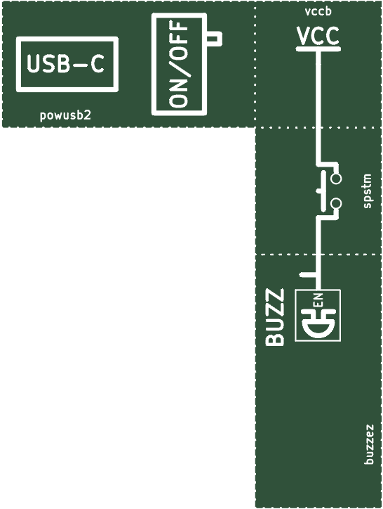
Buzzer (buzz-gb-0)
EN is short for enable. Putting VCC on EN turns the buzzer on.
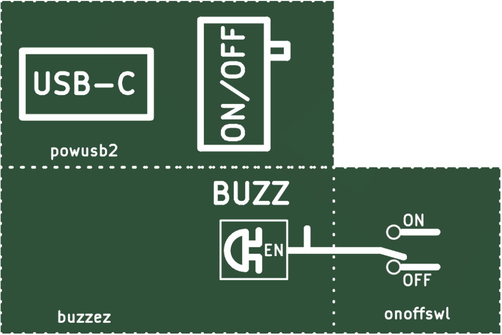
Putting GND on the EN pin turns off the buzzer. So does leaving it floating.
Day Alarm (alarm-gb-0)
As soon as this circuit senses light, it rings the alarm.
NOT Gate (not-gb-0)
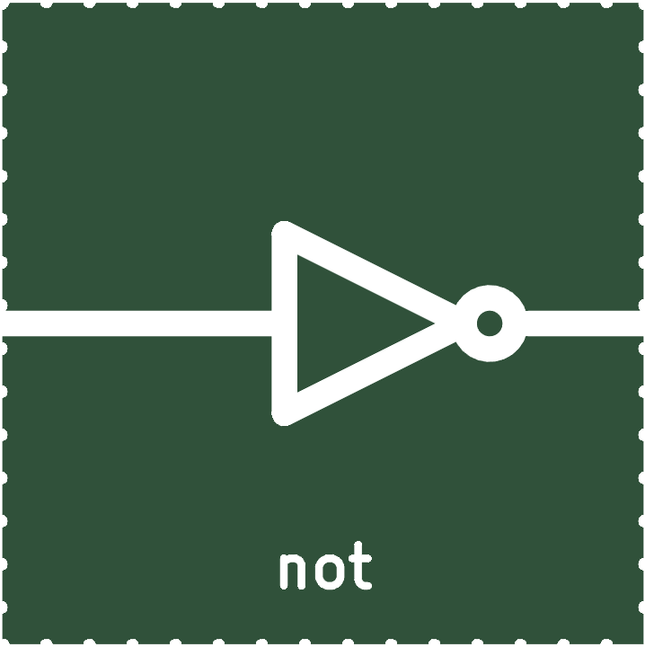
This is an example of a logic gate. It takes in a 1 (VCC) or a 0 (GND) on the left and outputs the opposite on the right.
Be careful with logic gates! It’s easy to break them. Be sure to turn off power before you move this symbol. Be sure to not put GND on the outputs of any logic gate.
It’s very easy to break components if they’re hooked up incorrectly. For the most part, symbols are very reliable even if incorrectly hooked up. This isn’t always the case, though.
Connecting wires together is called shorting. Shorting GND to VCC heats things up a lot and can easily break components.
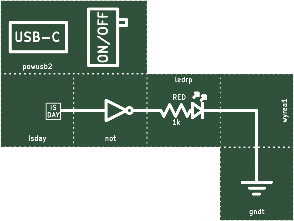
Nightlight (nightlight-gb-0)
This circuit turns on a light when no light is detected.
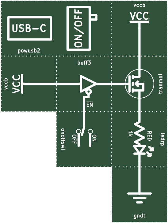
Three State Buffer (buff3-gb-0)
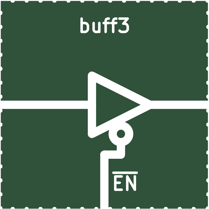
This is called a three-state buffer or tri-state buffer. The output is to the right, the input is from the left.
The bottom pin is called EN. The bar above the EN means that the pin is enabled when there is a 0 on it. These pins are called active low.
If EN is enabled (0), the output equals the input. If EN is disabled (1), then the output is left floating.
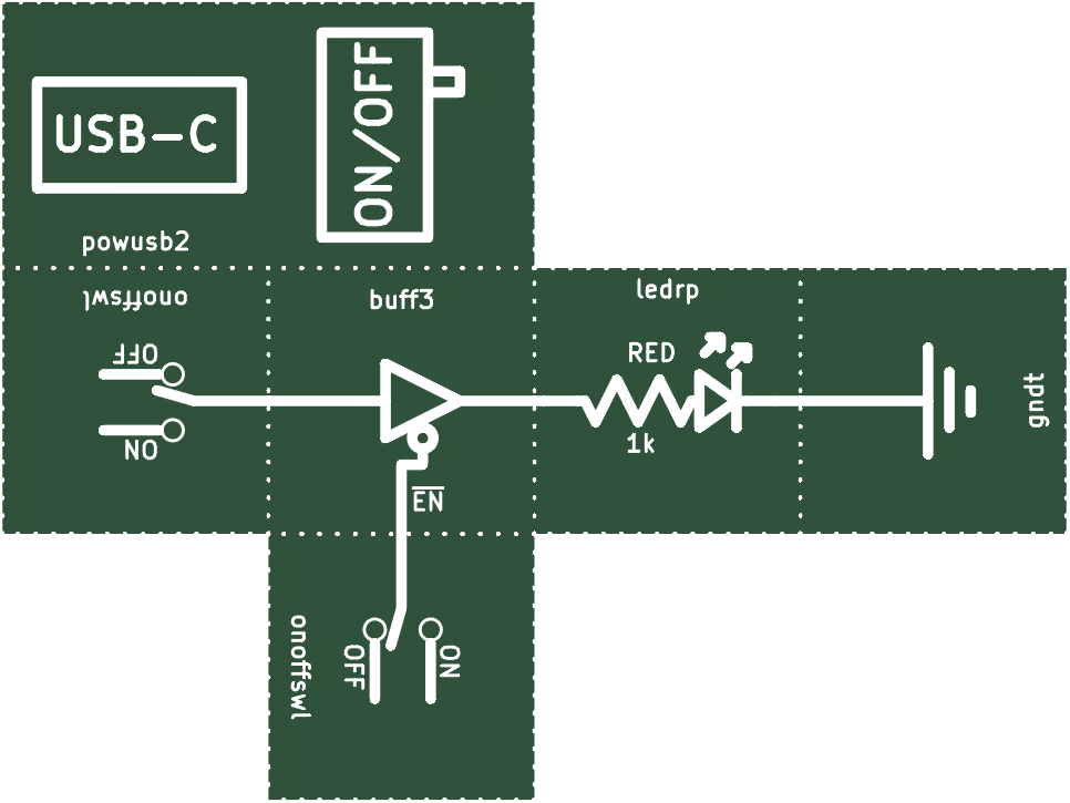
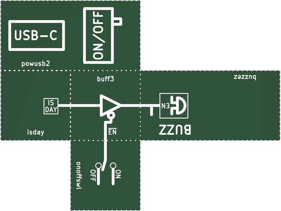
Alarm On/Off (alarm-toggle-gb-0)
This alarm turns on when it’s daytime. However, using a buffer, it can be disabled.
Buzz Button (buzz-spstm-gb-0)
OR Gate (or-gb-0)
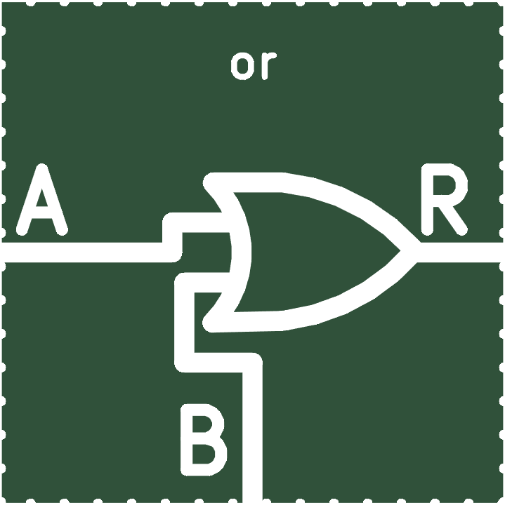
This is an OR gate. If either input is VCC, it outputs VCC. Otherwise it outputs GND.
We call VCC high, true, or 1. We call GND low, false, or 0.
This is a truth table for the OR gate. It tells you what the output is given inputs.
| Input A | Input B | Output R |
| 0 | 0 | 0 |
| 0 | 1 | 1 |
| 1 | 0 | 1 |
| 1 | 1 | 1 |

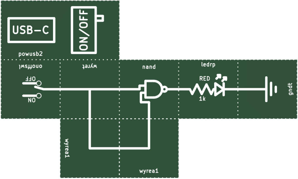
NAND Gate (nand-gb-0)
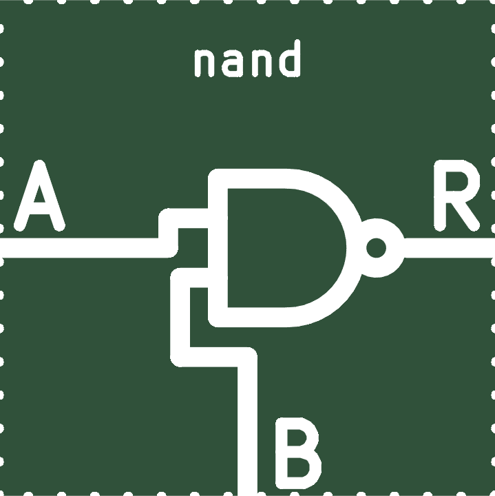
This is a NAND gate. If both inputs are 1, it outputs 0. Otherwise, it outputs 1.
| Input A | Input B | Output R |
| 0 | 0 | 1 |
| 0 | 1 | 1 |
| 1 | 0 | 1 |
| 1 | 1 | 0 |
Fun fact: All other logic gates can be made using just NAND gates! NAND gates may seem a bit strange. However, these are one of the most useful logic gates.
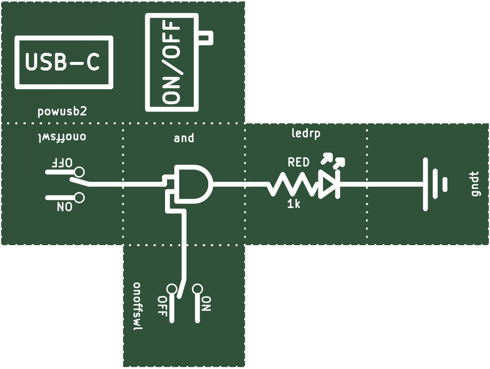
AND Gate (and-gb-0)
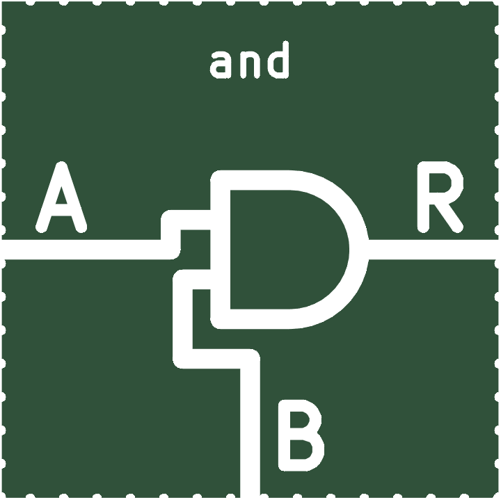
This is an and gate. If both inputs are 1, it outputs 1. Otherwise, it outputs 0.
| Input A | Input B | Output R |
| 0 | 0 | 0 |
| 0 | 1 | 0 |
| 1 | 0 | 0 |
| 1 | 1 | 1 |
Making a NAND be a NOT (nand-as-not-gb-0)
You can make a NAND gate into a NOT gate. This is one reason why they’re so useful.
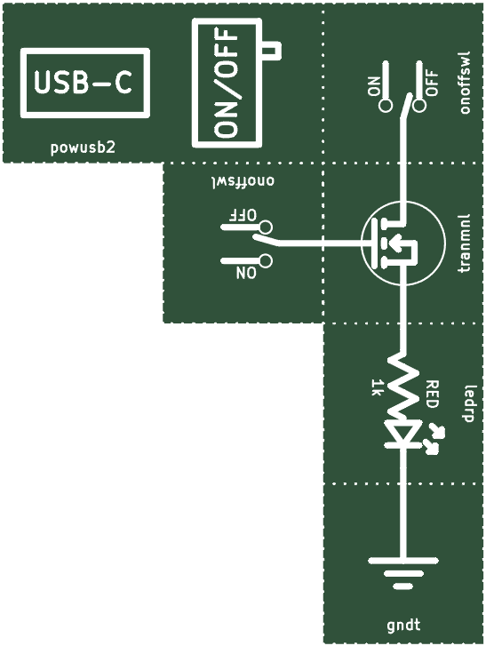
MOSFET (tranmnl-gb-0)
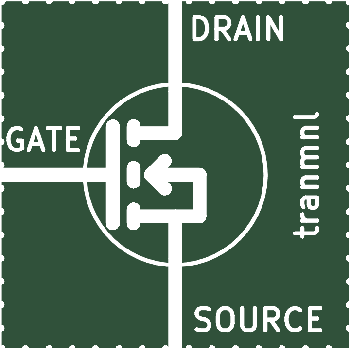
This is called a transistor. This type of transistor is called an n-channel enhancement mode MOSFET.
Floating MOSFETs (tranmnl-float-gb-0)
If a MOSFET gate is turned on, but then the gate is completely disconnected, it stays on. This is because a small charge remains on the gate. Try touching the gate. It should dissipate the charge.
NAND from a NAND (nand-nand-gb-0)
The bubble on the end of a NAND gate symbolizes a NOT. To illustrate this, we use an AND gate and a NAND gate to make a NAND gate.